      |
|
||
|
|
||
This chapter is intended as an introduction into the basic concepts of a CAD system. If you are used to working with CAD systems you might want to skip this chapter. Please note that the concepts mentioned in this chapter are all later described in detail.
Entities are graphical objects in a CAD system. Typical entities which are supported by most CAD systems are: points, lines and circular and elliptical arcs. More complex and CAD specific entities include polylines, texts, dimensions, hatches and splines.
Every entity has certain attributes such as its color, line type and line width.
A basic concept of computer aided drafting is the use of layers to organize and structure a drawing. Every entity of a drawing is on exactly one layer and each layer can contain any number of entities. Typically, all entities with a common 'function' or with common attributes are constructed on the same layer. Every layer has attributes (color, line width, line style) and the entities on a layer usually inherit their attributes from the layer they are placed on.
Figure 1 shows an example drawing that uses layers. All dimensions of the drawing are placed on a layer named 'dimensions'. The color of all 'dimension' entities isdefined by the layer and can be easily changed by changing the color of the layer 'dimensions'. The drawing can also be shown without any dimensions by hiding layer 'dimensions'.
Historically, in manual drafting, a similar approach has been used. Different building systems, such as wiring and air conditioning were often drawn on separate transparent sheet of paper. These sheets were then overlaid on one another to produce the final drawing.

Figure 1:
Example drawing with layers.
A block is a named group of entities. Blocks can be inserted into the same drawing more than once at different locations, with different attributes, scaling factors and rotation angles (see Figure 2). Such instances of a block are usually called 'inserts'. Inserts have attributes just like other entities. An entity that is part of an insert can have its own attributes, inherit its attributes from the layer it is placed on, or inherit them from the insert it is part of. Once created, inserts are still dependent on the block they instantiate. The power of inserts is, that you can modify a block and all inserts that were previously made from that block will be updated to reflect the changes.

Figure 2: Three instances of a
block (inserts) with different attributes, angles and scaling factors.
In many ways, CAD is similar to traditional drafting. When drawing a plan or a view of an object on a paper, you would use tools such as a ruler to draw lines. CAD systems offer many tools to achieve the same goal. The big advantage of a CAD system is the fact that you can change every entity of your drawing easily after you have created it. This might be one of the more difficult things to learn when moving from paper to CAD. When working with a CAD system you will very often create lines that will not be on the final printout or which don't have the correct length and need to be trimmed later (see Figure 3). A common mistake of CAD beginners is wanting to create the final drawing right away. Never hesitate to create an auxiliary construction if it helps you to define or verify a part of your drawing.
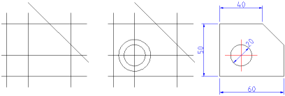
Figure
3: Three possible steps to quickly
create a drawing using supportive constructions and the ability of a CAD
system to change existing entities.
A good understanding of how the most common coordinate systems work is absolutely essential if you are to make the best use of any CAD program. If you are not familiar with coordinates it is highly recommended that you take some time to familiarize yourself with this fundamental concept.
The origin (or origin point) of the drawing is the point where the X and Y axis cross each other. It is also the absolute zero point of the drawing.
In addition to the absolute zero point, there is also a relative zero point in QCad. The relative zero point can be moved to any location by the user as a temporary reference for a local construction.
The Cartesian coordinate system is the standard coordinate system that is usually used if no other system is specified. In the Cartesian coordinate system, the position of a point can be described by its distance from two axes, X and Y. Cartesian coordinates are usually written in the format:
x-ordinate,y-ordinate
For example the coordinate 3.5,7 is located 3.5 units to the right and 7 unit to the top of the origin.

Figure
4: Absolute Cartesian coordinate
40,30.
Cartesian coordinates can also originate in a position different from the origin. In that case we talk about 'relative coordinates'. There is no standard notation for relative Cartesian coordinates, but in QCad they are written in the format:
@x-ordinate,y-ordinate

Figure
5: Relative Cartesian coordinate
@30,10.
Polar coordinates use a distance and an angle to describe the position of a point. The angle 0 is always pointing to the right on your screen (east). In QCad, polar coordinates are noted in the format:
distance<angle

Figure
6: Absolute Polar coordinate
50<37.
Just like Cartesian coordinates, polar coordinates can also originate in a position different from the origin. In QCad, relative polar coordinates are written in the format:
@distance<angle

Figure
7: Relative Polar coordinate
@31.6<18.4
Whenever you need to specify a coordinate in QCad, you can use the snap functions. They allow you to precisely select grid points or significant points on existing objects such as endpoints, midpoints, centers or intersections between entities.
Entities can be added to a drawing with various drawing tools or by duplicating existing entities. To draw an entity means to define all points and parameters that define the entity, such as the endpoints of a line.
Before an entity can be deleted, duplicated, or transformed, it must be selected. Entity selection is one of the most basic of CAD operations. However, selecting the right entities for an operation is not always trivial. QCad offers a wide variety of selection tools to quickly select groups of entities, entities within a range, connected entities, etc.
Deleting an entity means to remove it from the drawing. In QCad, all features that have to do with deleting entities are grouped with the modification features.
Existing entities can be modified in many ways. Basic modifications include translation, rotation, reflection, and scaling. These operations do not alter the characteristic geometry of the affected entities. Other modifications change an entity more fundamentally (for example trimming, extending or stretching)
Unlike in manual drafting, there is no need in CAD to determine in advance the sheet size and drawing scale. There is no drawing scale: all sizes and distances are specified using their full-scale values. A 10 meter object is drawn as a 10 meter object. Only at the printing stage, a drawing scale needs to be specified to fit the drawing on a paper. The drawing model itself is not affected by this and always remains in the original 1:1 scale.
On the screen, the user can adjust the currently visible area of the drawing by zooming in to view more detail or zooming out to view a wider extent. Another important viewing operation in CAD is panning. To see another portion of the drawing without changing the display scale, a user pans to it by "moving" a rectangular display window until it is over the desired spot.
|